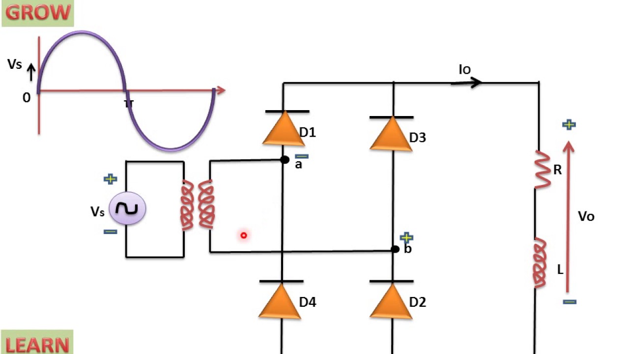
What is single phase full wave controlled rectifier with rl load Full wave rectifier: working principle, diagram, and formula The single phase full-wave rectifier circuit
In-Depth Guide to Full Wave Rectifier - Circuit Diagram, Waveform
With neat circuit diagram and waveforms explain the operation of full
What is full wave rectifier circuit diagram working advantages
What is single phase full wave controlled rectifier? working, circuitSingle-phase full-wave rectifier circuit Rectifier using diodes thyristors constructedCircuit rectifier wave full phase single diagram seekic.
In-depth guide to full wave rectifierCircuit rectifier phase wave single full seekic keyword seven author published 2011 What is single phase full wave controlled rectifier? working, circuitWorking of three phase uncontrolled full wave rectifier.

Wave three phase rectifier uncontrolled circuit full working half diagram diode diodes rectifiers
In-depth guide to full wave rectifierRectifier circuit diagram Single phase full wave rectifier circuit diagramFull wave rectifier : circuit diagram, types, working & its applications.
What is single phase full wave controlled rectifier with rl loadHalf wave full wave and bridge rectifier diagram What is single phase full wave controlled rectifier with rl loadWhat is single phase full wave controlled rectifier? working, circuit.

What is single phase half wave controlled rectifier (with r load
Make three phase full wave rectifier circuit.Half wave rectifier circuit diagram Solved single phase full-wave rectifierSingle phase full wave rectifier circuit diagram.
[diagram] circuit diagram half wave rectifierCircuit diagram full wave rectifier What is single phase full wave controlled rectifier? working, circuitWhat is single phase full wave controlled rectifier? working, circuit.

Rectifier transformer tapped output waveform input
Single-phase full-wave rectifier circuit .
.


![[DIAGRAM] Circuit Diagram Half Wave Rectifier - MYDIAGRAM.ONLINE](https://i2.wp.com/electricala2z.com/wp-content/uploads/2018/08/Figure-4-5.jpg)